Objective for this week: for this week I draw the
circuit and test all component function for this trolley follower.
1. Draw the schematic diagram using PROTEL99SE.

software for design schematic
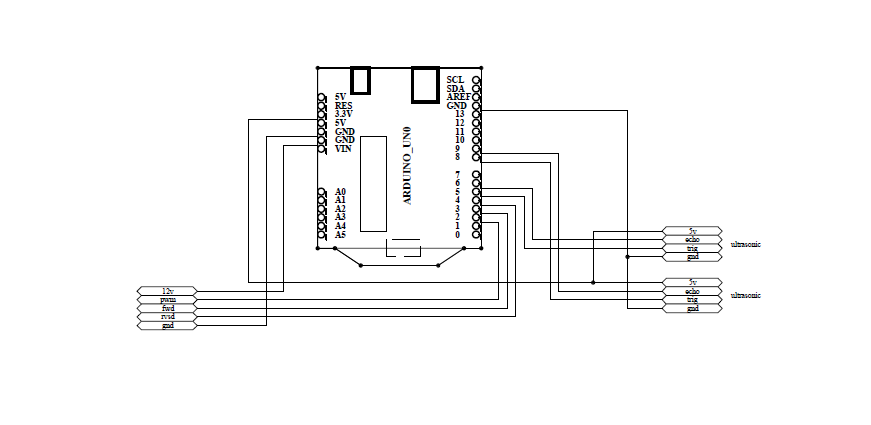
This schematic diagram circuit for trolley follower
for this schematic circuit for this project, I use 2 of sensor ultrasonic and 2 motor for control movement of trolley follower when the trolley moving with customer.
2. Test all component for this trolley follower.
I test arduino, sensor, resistor, capacitor and all component to test performance and function or not of all component.


this picture for time test all component
In arduino code Write a
HIGH or a LOW value to a digital pin.
If the pin has been
configured as an OUTPUT with pinMode(), its voltage will be set to the
corresponding value: 5V for HIGH, 0V (ground) for LOW.
If the pin is
configured as an INPUT, digitalWrite() will enable (HIGH) or disable (LOW) the
internal pullup on the input pin. It is recommended to set the pinMode() to
INPUT_PULLUP to enable the internal pull-up resistor.
No comments:
Post a Comment